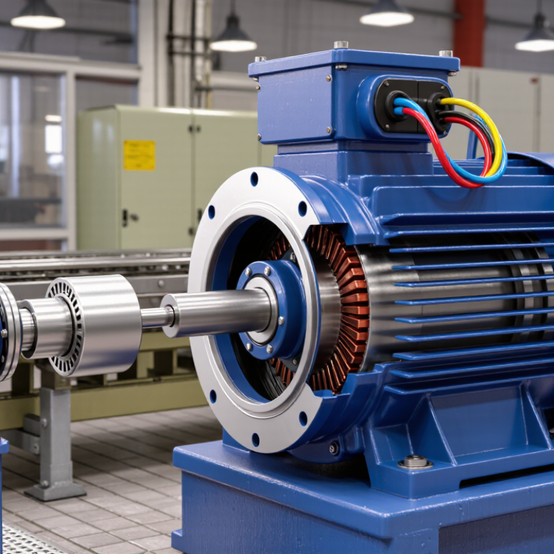
Understanding how does an industrial electric motor work begins with a simple idea: electricity creates a controlled magnetic force. Inside the motor, the stator remains fixed while the rotor turns on a shaft. Copper windings in the stator receive alternating current and produce a rotating magnetic field. That field induces current in the rotor, creating torque and mechanical motion.
The details become more practical in a factory. A motor may drive a conveyor, pump, compressor, or large fan for thousands of hours. Bearings support the rotating shaft, insulation protects the windings, and a cooling fan carries heat away from the housing. In many installations, a variable frequency drive adjusts speed and starting torque. This reduces mechanical shock and can lower energy use, but incorrect settings may cause overheating or unstable operation.
Small details matter.
This guide connects electromagnetic theory with real maintenance observations. A technician may hear a damaged bearing before vibration sensors confirm it. A hot terminal can reveal loose connections, poor airflow, or excessive load. These clues are useful, though not always conclusive. Motor faults can share similar symptoms, so professional testing remains essential. Measurements such as current balance, insulation resistance, temperature, and vibration help verify the diagnosis. The explanation is intentionally practical, but it cannot replace the manufacturer’s documentation or qualified electrical inspection. Industrial systems differ in design, duty cycle, voltage, and environmental conditions. Even a reliable motor can fail when ignored.
How Does an Industrial Electric Motor Work?
Three-Phase Power at 50–60 Hz Creates a Rotating Magnetic Field
An industrial electric motor converts electrical energy into mechanical rotation. Its stator contains three-phase windings arranged around a stationary iron core. When 50–60 Hz alternating current enters these windings, each phase reaches its peak at a different time. Their combined magnetic fields create smooth rotation inside the stator.
The rotating field cuts across the rotor conductors. This action induces current in the rotor, producing a second magnetic field. The two fields interact, and torque begins turning the shaft. The rotor usually moves slightly slower than the magnetic field. This difference is called slip, and it is necessary for induction to occur. Without slip, torque would disappear. The explanation sounds clean, but real motors are less tidy. Heat, bearing friction, voltage imbalance, and dust can change performance. During field checks, technicians often compare current readings across all three phases. Unequal readings may reveal a connection problem or mechanical overload.
Tips: Keep frequency and voltage within the motor’s rated range. Check ventilation paths regularly, especially in dusty areas. Listen for unusual humming or grinding. A thermal scan can expose hot terminals before insulation fails. Do not assume a quiet motor is healthy. Some electrical faults remain invisible until the load increases. For critical equipment, record vibration, temperature, and current over time. Trends usually tell a clearer story than one inspection. Be cautious with simplified diagrams; actual rotor designs vary.
| System or Component | What Happens | Representative Data | Why It Matters |
|---|---|---|---|
| Three-phase stator supply | Three alternating currents are separated by 120 electrical degrees and flow through the stator windings. | Frequency: 50–60 Hz Phase displacement: 120° |
The phase sequence produces a continuously rotating magnetic field without mechanical switching. |
| Stator core and windings | Insulated copper or aluminum conductors are placed in slots of a laminated steel core to concentrate magnetic flux. | Core construction: laminated electrical steel Typical winding connection: star or delta |
Laminations reduce eddy-current losses, while the winding arrangement establishes the rotating field. |
| Synchronous speed | The speed of the rotating magnetic field depends on supply frequency and the number of stator poles. | Formula: ns = 120f / P ns = synchronous speed in rpm; f = frequency in Hz; P = poles |
More poles produce a slower rotating field; higher frequency produces a faster rotating field. |
| Typical synchronous speeds | Theoretical field speeds are calculated before slip is considered. |
2 poles: 3,000 rpm at 50 Hz; 3,600 rpm at 60 Hz 4 poles: 1,500 rpm at 50 Hz; 1,800 rpm at 60 Hz 6 poles: 1,000 rpm at 50 Hz; 1,200 rpm at 60 Hz 8 poles: 750 rpm at 50 Hz; 900 rpm at 60 Hz |
These values help select a motor for pumps, fans, compressors, conveyors, and other industrial loads. |
| Rotor induction | The rotating stator field cuts the rotor conductors and induces rotor current through electromagnetic induction. | Rotor types: squirrel-cage or wound rotor Rotor current frequency is lower than supply frequency during normal operation. |
No direct electrical connection to a squirrel-cage rotor is required, which improves reliability and reduces maintenance. |
| Slip | The rotor must turn slightly slower than the rotating magnetic field to maintain relative motion and induce current. | Slip formula: s = (ns − nr) / ns Typical full-load slip: approximately 1–5% |
Without slip, rotor current and torque would fall substantially because there would be little relative motion. |
| Torque production | The interaction between the stator magnetic field and rotor magnetic field creates electromagnetic torque. | Mechanical power relationship: P = T × ω P = power; T = torque; ω = angular speed |
Torque transfers electrical energy into mechanical rotation at the shaft. |
| Rotor and shaft | The rotor spins inside the stator, and the shaft delivers torque to the connected machine. | Common shaft support: rolling-element bearings Rotation direction depends on phase sequence. |
Interchanging any two supply phases reverses the rotating-field direction and typically reverses motor rotation. |
| Frequency and speed control | An adjustable-frequency drive changes the supply frequency and voltage to regulate motor speed and torque. | Speed is approximately proportional to frequency below the motor's base frequency, subject to slip and load. | Variable-frequency operation can provide controlled starting, energy savings, and process-speed adjustment. |
| Energy losses and heat | Electrical resistance, magnetic hysteresis, eddy currents, friction, windage, and load-related losses produce heat. | Efficiency: generally increases with motor size and load optimization; actual efficiency varies by design and operating point. | Cooling systems and correct loading help protect insulation, bearings, and other components from excessive temperature. |
Note: Actual speed, current, torque, efficiency, temperature rise, and starting performance depend on motor design, supply voltage, load, enclosure, cooling method, and operating conditions.
Alternating current energizes the stator windings. A rotating magnetic field forms. The rotor follows this field and produces torque at the shaft.
The air gap separates the stationary stator from the rotating rotor. It also lets magnetic flux cross between them. Too much clearance weakens magnetic coupling.
Uneven clearance can cause vibration, noise, and extra bearing stress. It may also increase energy use. The motor can still appear normal.
Bearings keep the rotor centered inside the air gap. They carry forces from belts, couplings, and magnetic effects. Some bearings also handle axial loads.
Proper lubrication reduces friction, heat, and surface damage. Poor grease condition can accelerate wear. Small losses become serious during continuous operation.
Yes. Bearing damage can waste energy before failure becomes obvious. Technicians should check temperature, vibration, grease, and shaft movement. Quiet operation proves little.
Some models convert up to 96% of input power into mechanical output. This figure depends on load, voltage, cooling, and maintenance. It is not guaranteed everywhere.
No. An oversized motor may run inefficiently at light load. Correct sizing can save more energy than selecting a higher class. This is easy to overlook.
Misalignment, contamination, poor cooling, and a soft mounting base can reduce performance. A clean air path helps remove heat. Field conditions matter more than nameplate claims alone.
They should compare current, temperature, vibration, load, and operating hours. Efficiency curves are more useful than one nameplate number. Laboratory results are only part of the picture.
How does an industrial electric motor work? It converts electrical energy into mechanical motion by using the interaction between magnetic fields. In a typical three-phase motor, alternating current at 50–60 Hz flows through the stator windings and produces a rotating magnetic field. This moving field passes across the air gap and induces current in the rotor through electromagnetic induction. The rotor then develops its own magnetic field and begins to follow the stator field, creating torque.
The rotor must operate slightly slower than the rotating magnetic field, a difference known as slip. Under normal conditions, slip typically remains between 1% and 5%, allowing continuous torque production. Bearings support the rotating assembly and help transfer mechanical power smoothly to the shaft, while the air gap enables magnetic coupling between the stator and rotor. High-efficiency IE3 and IE4 motors can convert up to 96% of input power into useful output, reducing energy losses during operation.

 KPR Motor